The DeWALT DW745 Manual is your comprehensive guide to mastering the operation and maintenance of your Heavy-Duty 10" Job Site Table Saw. This detailed manual includes step-by-step instructions, safety guidelines, and troubleshooting tips tailored to the DeWALT DW745 model. Whether you are a professional carpenter or a DIY enthusiast, the DeWALT DW745 Manual provides you with all the essential information needed to keep your table saw in top working condition and ensure precise, efficient cutting. Download your free digital copy today and ensure your projects run smoothly with the DeWALT DW745.
Definitions: Safety Guidelines
The definitions below describe the level of severity for each signal word. Please read the manual and pay attention to these symbols.
- DANGER: Indicates an imminently hazardous situation which, if not avoided, will result in death or serious injury.
- WARNING: Indicates a potentially hazardous situation which, if not avoided, could result in death or serious injury.
- CAUTION: Indicates a potentially hazardous situation which, if not avoided, may result in minor or moderate injury.
- CAUTION: Used without the safety alert symbol indicates a potentially hazardous situation which, if not avoided, may result in property damage.
SAVE THESE INSTRUCTIONS
General Safety Rules
Grounding Instructions
If saw is of grounded construction, read the following instructions.
All Grounded, Cord-Connected Machines
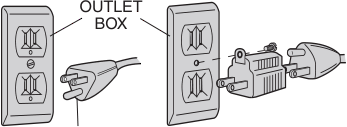
In the event of a malfunction or breakdown, grounding provides a path of least resistance for electric current to reduce the risk of electric shock. This machine is equipped with an electric cord having an equipment-grounding conductor and a grounding plug. The plug must be plugged into a matching outlet that is properly installed and grounded in accordance with all local codes and ordinances.
Double Insulation
If saw is of double-insulated construction, read the following instructions.
Double insulated tools are constructed throughout with two separate layers of electrical insulation or one double thickness of insulation between you and the tool’s electrical system. Tools built with this insulation system are not intended to be grounded. A double insulated tool is equipped with a two prong plug, which may be used in a properly grounded two-prong outlet.
Important Safety Instructions
- TO REDUCE THE RISK OF KICKBACK AND OTHER INJURIES, KEEP GUARDS IN PLACE and in working order at all times.
- REMOVE ADJUSTING KEYS AND WRENCHES. Form habit of checking to see that keys and adjusting wrenches are removed from tool before turning it on.
- KEEP WORK AREA CLEAN. Cluttered areas and benches invite accidents.
- DO NOT USE IN DANGEROUS ENVIRONMENT. The use of power tools in damp or wet locations or in rain can cause shock or electrocution.
- KEEP CHILDREN AWAY. All visitors should be kept at a safe distance from work area. Your shop is a potentially dangerous environment.
- MAKE WORKSHOP CHILDPROOF with padlocks, master switches, or by removing starter keys. The unauthorized start-up by a child or visitor may result in injury.
- DO NOT FORCE TOOL. It will do the job better and be safer at the rate for which it was designed.
- USE RIGHT TOOL. Don’t force tool or attachment to do a job for which it was not designed. Using the incorrect tool or attachment may result in personal injury.
Additional Safety Rules for Table Saws
- AVOID AWKWARD POSITIONS, where a sudden slip could cause a hand to move into a saw blade.
- NEVER REACH IN BACK OF, OR AROUND, THE CUTTING TOOL with either hand to hold work piece.
- KEEP ARMS, HANDS AND FINGERS AWAY from the blade to prevent serious injury.
- Use a PUSH STICK OR PUSH BLOCK that is appropriate to the application. The push stick provides sufficient distance between the hand and the blade.
General Safety Rules
- DO NOT LEAVE TOOL RUNNING UNATTENDED. TURN POWER OFF. Don’t leave tool until it comes to a complete stop. Serious injury can result.
- DO NOT OPERATE ELECTRIC TOOLS NEAR FLAMMABLE LIQUIDS OR IN GASEOUS OR EXPLOSIVE ATMOSPHERES. Motors and switches in these tools may spark and ignite fumes.
- STAY ALERT, WATCH WHAT YOU ARE DOING, AND USE COMMON SENSE. Do not use the machine when you are tired or under the influence of drugs, alcohol, or medication.
- DO NOT ALLOW FAMILIARITY (gained from frequent use of your saw) to replace SAFETY RULES. Always remember that a careless fraction of a second is sufficient to inflict severe injury.
Definitions of Terms Used Throughout the Manual
The following terms will be used throughout the manual and you should familiarize yourself with them.
- Through-sawing: Refers to any cut that completely cuts through the work piece.
- Push Stick: Makes it possible to control the work piece when hands would be too close to the blade.
- Kickback: When the saw blade binds in the cut, the work piece can be violently thrown out of the work.
- Freehand: Refers to cutting without using a cutting guide such as a fence.
Specifications
- Power : 15 AMP
- Miter Angle : 60° L and R
- Bevel Angle : 0° to 45° L
- Blade Size : 10" (254 mm)
- Max Cut Depth :
- 0° Bevel : 3-1/8" (79 mm)
- 45° Bevel : 2-1/4" (57 mm)
- RPM, no load : 3850
Unpacking
Open the box and slide the saw out, as shown in Figure 1. Carefully unpack the table saw and all loose items from the carton. Examine all parts to make sure that parts have not been damaged during shipping. If any parts are missing or damaged, contact your dealer to replace them before attempting to assemble the tool.
Refer to Figure 2 for the loose items and hardware included with the saw:
- Rip fence
- Arbor wrench and spindle wrench (attached to saw base)
- Blade guard
- Miter gauge
- Push stick (attached to saw base)
- Extra guard shims
Figure 1
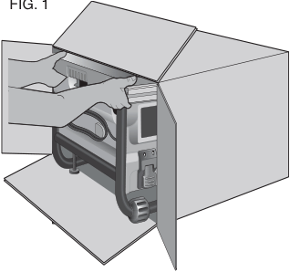
Figure 2
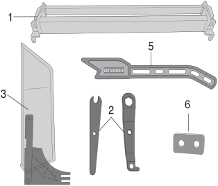
Figure 3
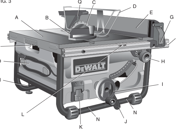
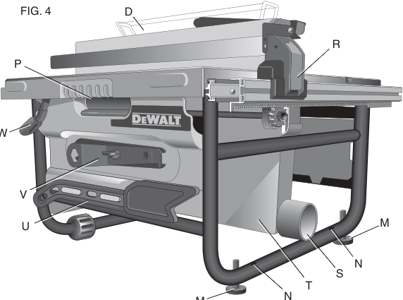
- A. Table
- B. Miter gauge
- C. Blade
- D. Blade guard
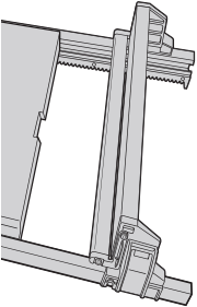
- E. Fence
- F. Fence rails
- G. Rip fence front latch
- H. Fine adjustment knob
- I. Blade height adjustment wheel
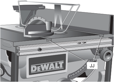
- J. Bevel lock lever
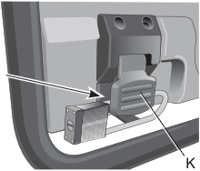
- K. ON/OFF switch
- L. Rip fence indicator
- M. Adjustable feet
- N. Mounting holes
- O. Cord wrap
- P. Handle
- Q. Anti-kickback teeth
- R. Rip fence rear latch
- S. Dust collection port
- T. Dust shroud
- U. Push stick
- V. Arbor wrench, spindle wrench
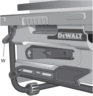
- W. Rail lock lever
Assembly
Assemble Your Saw in the Following Order
- Rip fence (NOTE: Adjust rip scale before proceeding; refer to Rip Scale Adjustment.)
- Blade guard
- Push stick
- Miter gauge (if required for application)
- Blade height adjustment crank
Tools needed for assembly include a Phillips screwdriver and the wrenches included with your saw.
Blade
Attaching and Replacing the Blade
- Raise the saw blade arbor to its maximum height by turning the blade height adjustment wheel (I) clockwise.
- If replacing the blade, remove the blade guard (D) and throat plate (X) prior to installing the new blade. (Refer to To Remove Blade Guard and To Remove Throat Plate.)
- NOTE: It may be easier to change the blade with the saw blade beveled to 45°.
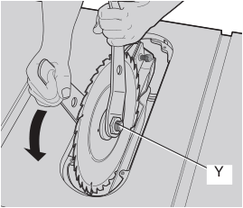
- Remove the arbor nut (Y) and outer washer (Z) and set aside.
- Place the blade (C) on the arbor making sure the teeth of the blade point downward and toward the front of the saw.
- Place the outer washer (Z) against the blade, raised side out and tighten the arbor nut against the washer as far as possible by hand. Ensure that the outer washer and arbor nut are free of dust and debris before installing.
- To further tighten the arbor nut (Y), use the open ended spindle wrench (supplied) to keep the spindle from rotating.
Rip Fence
The rip fence can be installed on the left or right side of your table saw.
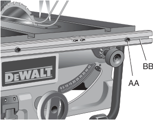
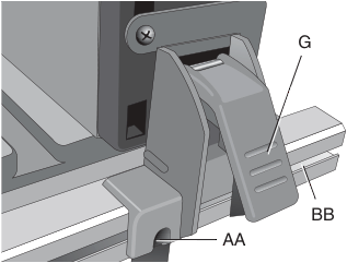
To Assemble the Rip Fence
- Align the locator screw (AA) on the fence rail (F) with the fence head slot and align the latch (G) with the opening (BB).
- Secure the rip fence by snapping the latches onto the rails.
Throat Plate
To Remove the Throat Plate
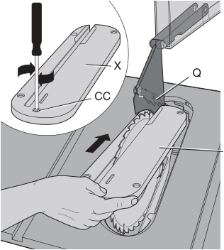
- Remove the throat plate (X) by turning the cam lock screw (CC) in the front middle 1/4 turn as shown.
To Attach the Throat Plate
- Align the throat plate as shown in Figure 9, and insert the tabs on the back of the throat plate into the holes on the back of the table.
- Rotate cam out of the way until the front of throat plate drops into place. Secure by rotating 1/4 turn (when cam lock is under the table holding the throat plate in place).
- The throat plate includes four adjustment screws which raise or lower the throat plate.
Blade Guard
To Attach the Blade Guard
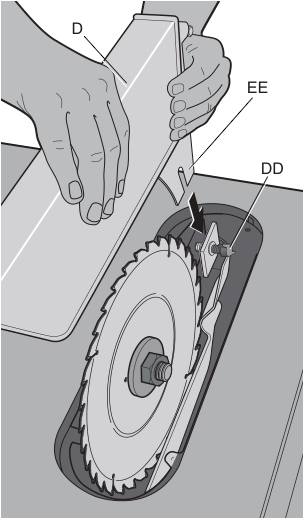
- Remove the throat plate (Refer to Throat Plate).
- Raise the saw blade arbor to its maximum height by turning the blade height adjustment wheel (I) clockwise.
- Loosen the wing nut (DD) (minimum of three complete turns).
- Insert the splitter (EE) into the locking mechanism.
- Tighten the wing nut against the locking mechanism.
Adjusting the Blade Guard
- Raise the blade (C) to its highest level.
- Remove the blade guard (D) and blade.
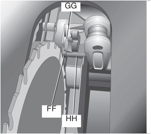
- Remove the two screws (FF) holding the guard retainer (GG) using a 5 mm hex wrench (HH).
- Add or remove shims (II) to align the splitter to the blade.
- Reassemble, torquing the screws securely (FF). Make sure the splitter is aligned properly to the blade. (Refer to To Attach the Blade Guard under Blade Guard.)
Push Stick
To Attach the Push Stick (Fig. 4)
- Align the slots in the handle of the push stick with the mounting pins on the saw housing.
Miter Gauge
To Attach the Miter Gauge
- The DW745 includes a miter gauge for crosscutting board materials.
Bench Mounting
To Bench Mount Saw
- Center the saw on the desired, stable work surface.
- Drive four 3-1/2” (88.9 mm) long screws through the holes in the metal frame.
- Ensure the saw is firmly mounted before use.
Connecting Saw to Power Source
On-Off Switch
Rip Fence Operation
Rail Lock Lever (Fig. 4)
The rail lock lever (W) locks the fence in place preventing movement during cutting.
Work Support Extension (Fig. 15, 16)
Your table saw is equipped with a work support extension to support work that extends beyond the saw table.
Adjustments
Rip Scale Adjustment (Calibrating Rip Scale)
Blade Alignment Adjustment (Blade Parallel to Miter Slot)
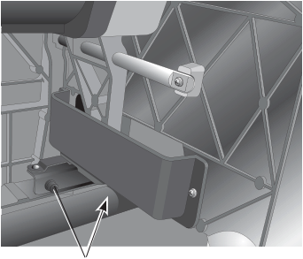
Bevel Adjustment (Fig. 21)
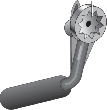
The bevel lock lever (J) may need adjustment to maintain lock force.
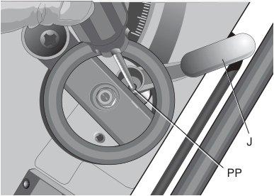
Bevel Lock Adjustment (Fig. 21)
Part A – Adjusting the Bevel Scale System (Fig. 22, 23)
- Remove the blade guard from the saw and raise the blade all the way up in the table.
- Unlock the bevel lock lever and loosen the bevel stop screw.
- Place a square against the table and blade. NOTE: Be sure to place the square between the teeth on the blade to ensure an accurate measurement.
- Adjust the bevel angle until the blade is flat against the square. Lock the bevel lock lever.
- Move the bevel stop cam until it firmly contacts the trunnion casting. Tighten the bevel stop screw.
- Repeat procedure at 45° using a triangle or speed square.
Part B – Adjusting the Bevel Scale Pointer
Check the bevel scale angle. If the pointer does not read 0°, loosen the pointer screw and move it to the 0° mark on the bevel scale. Retighten the pointer screw.
MITER GAUGE ADJUSTMENT (Calibrating Miter Gauge Pointer)
Your miter gauge features adjustable stops at 90° and 45° left and right.
- To adjust the miter gauge, loosen the screw and move to desired position. Tighten the screw against the stop plate (Fig. 24).
Saw Blades
- The saw blade furnished with your new saw is a 10" (254 mm) combination blade, used for crosscutting (across the grain) and ripping (with the grain) through the material. The center hole to fit on the arbor is 5/8" (16 mm) diameter (.625"). This blade will produce a good quality cut for most applications.
- There are many types of blades available to do specific and special jobs such as crosscut only, rip only, hollow ground, thin plywood, paneling, etc.
- Use only saw blades designed for maximum safe operating speeds of 5,000 RPM or greater.
- Saw blades should always be kept sharp. It is recommended that you locate a reputable sharpening service to sharpen your blades when needed.
Kickback
Kickback is a dangerous condition! It is caused by the work piece binding against the blade. The result is that the work piece can move rapidly in a direction opposite to the feed direction. During kickback, the work piece could be thrown back at the operator. It can also drag the operator's hand back into the blade if the operator's hands are at the rear of the blade. If kickback occurs, turn the saw OFF and verify the proper functioning of the splitter, anti-kickback teeth and guards before resuming work.
WARNING:
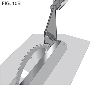
- Always use the guard and make certain it is in good working order. The guard's splitter helps prevent binding and the anti-kickback teeth on each side of the splitter minimize the possibility of kickback. Use extra caution until the work piece is through the splitter and has engaged anti-kickback teeth.
- Do not saw warped, bowed or cupped wood. The work piece must have one straight, smooth side to go against the rip fence or miter gauge. The work piece must sit flat on the table without rocking.
- Do not cut "freehand". Always use either the rip fence or the miter gauge. Never use both.
- Use extra care when the guard assembly cannot be used (during non-through cuts).
- Support large work pieces carefully. Allowing them to sag or droop can cause kickback.
Operation
- ALWAYS wear proper eye, hearing and respiratory equipment.
- Blade is tight.
- Bevel angle and height lock knobs are tight.
- If ripping, ensure fence lock lever is tight and fence is parallel to the blade.
- If crosscutting, miter gauge knob is tight.
- The blade guard is properly attached and the anti-kickback teeth are functioning.
- ALWAYS inspect the guard and splitter for proper alignment and operation and clearance with saw blade.
Failure to adhere to these common safety rules can greatly increase the likelihood of injury.
Ripping
There are two basic types of cutting with table saws: ripping and crosscutting. Cutting with the grain is ripping and cutting against the grain is crosscutting. With manmade materials, the distinction is made such that ripping is cutting to a different width and crosscutting describes cutting material across the shorter dimension.
Ripping:
Ripping Small Pieces
It is unsafe to rip small pieces. It is not safe to put your hands close to the blade. Instead, rip a larger piece to obtain the desired piece. When a small width is to be ripped and the hand cannot be safely put between the blade and the rip fence, use one or more push sticks. A pattern is included at the end of this manual to make push sticks. A push stick is included with the saw, located on the right-side panel. Use the push stick(s) to hold the work piece against the fence and push the work piece fully past the blade. See Figure 26.
- Lock the rip fence. Remove the miter gauge.
- Raise the blade so it is about 1/8" (3.2 mm) higher than the top of the work piece.
- Hold the work piece flat on the table and against the fence. Keep the work piece about 1" (25.4 mm) away from the blade. CAUTION: The work piece must have a straight edge against the fence and must not be warped, twisted or bowed. Keep both hands away from the proper hand position in Figure 25.
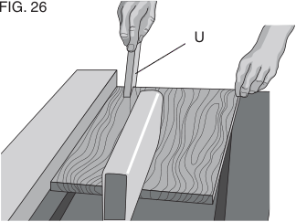
Figure 25: Proper Hand Position - Turn the saw on and allow the blade to come up to speed. Both hands can be used in starting the cut. When there is approximately 12" (305 mm) left to be ripped, use only one hand, with your thumb pushing the material, your index and second finger holding the material down and your other fingers hooked over the fence. Always keep your thumb along side your first two fingers and near the fence.
- Keeping the work piece against the table and fence, slowly feed the work piece rearward all the way through the saw blade. Continue pushing the work piece until it is clear of the guard and it falls off the rear of the table. Do not overload the motor.
- Never try to pull the work piece back with the blade turning. Turn the switch off, allow the blade to stop, raise the anti-kickback teeth on each side of the splitter if necessary and slide the work piece out.
- When sawing a long piece of material or a panel, always use a work support. A saw horse, rollers, or out feed assembly provides adequate support. Use supports for this purpose. The work support must be at the same height as the saw table.
Bevel Ripping
This operation is the same as ripping except the bevel angle is set to an angle other than zero degrees. WARNING: Before connecting the table saw to the power source or operating the saw, always inspect the guard and splitter for proper operation and clearance with saw blade. Check alignment after each change of bevel angle.
Crosscutting
The following illustrations show proper hand positions and auxiliary devices used to minimize risk of injury due to kickback.
Crosscutting:
- Remove the rip fence and place the miter gauge in the desired slot.
- Adjust the blade height so that the blade is about 1/8" (3.2 mm) higher than the top of the work piece.
- Hold the work piece firmly against the miter gauge with the path of the blade in line with the desired cut location. Keep the work piece an inch or so in front of the blade. KEEP BOTH HANDS AWAY FROM THE BLADE AND THE PATH OF THE BLADE (Fig. 27).
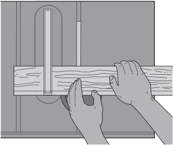
Figure 27: Proper Hand Position for Crosscutting - Start the saw motor and allow the blade to come up to speed.
- While using both hands to keep the work piece against the face of the miter gauge and the miter gauge tight against the table, slowly push the work piece through the blade.
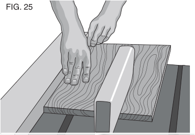
Figure 27: Holding Work Piece Flat Against the Table - Never try to pull the work piece with the blade turning. Turn the switch off, allow the blade to stop, and carefully slide the work piece out.
Bevel Crosscutting
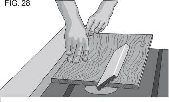
This operation is the same as crosscutting except that the bevel angle is set to an angle other than 0°. For proper hand position, refer to Figure 28.
Mitering
This operation is the same as crosscutting except the miter gauge is locked at an angle other than 0°. Hold the work piece FIRMLY against and miter gauge and feed the work piece slowly into the blade (to prevent the work piece from moving). See Figure 29.
Compound Mitering
This is a combination of bevel crosscutting and mitering. Follow the instructions for both bevel crosscutting and mitering.
Dust Collection
Your table saw is equipped with a dust shroud and dust collection port. For best results, connect a vacuum to the port at the rear of the saw. After extended use, the saw's dust collection system may become clogged. To clear the dust collection system:
- Unplug the saw.
- Turn the saw on its side, so the bottom, open part of the unit is accessible.
- Open the dust access door by removing the wing screws. Clean out the excess dust, and re-secure the access door with the wing screws.
Lubrication
- All motor bearings are permanently lubricated at the factory and no additional lubrication is needed.
- The height adjustment gear requires periodic cleaning and lubrication. If you have difficulty raising or lowering the blade, contact a DEWALT authorized service center.
Accessories
If you need assistance in locating any accessory, please contact DEWALT Industrial Tool Co., 701 East Joppa Road, Baltimore, MD 21286, call 1-800-4-DEWALT (1-800-433-9258) or visit our website www.dewalt.com.
Maintenance
Cleaning
Repairs
To assure product SAFETY and RELIABILITY, repairs, maintenance, and adjustments (including brush inspection and replacement) should be performed by a DEWALT factory service center, a DEWALT authorized service center, or other qualified service personnel. Always use identical replacement parts.
Three Year Limited Warranty
DEWALT will repair, without charge, any defects due to faulty materials or workmanship for three years from the date of purchase. This warranty does not cover part failure due to normal wear or tool abuse. For further detail of warranty coverage and warranty repair information, visit www.dewalt.com or call 1-800-4-DEWALT (1-800-433-9258). This warranty does not apply to accessories or damage caused where repairs have been made or attempted by others. This warranty gives you specific legal rights, and you may have other rights which vary in certain states or provinces.
In addition to the warranty, DEWALT tools are covered by:
- 1 YEAR FREE SERVICE: DEWALT will maintain the tool and replace worn parts used by normal use, for free, any time during the first year after purchase.
- 90 DAY MONEY BACK GUARANTEE: If you are not completely satisfied with the performance of your DEWALT Power Tool, Laser, or Nailer for any reason, you can return it within 90 days from the date of purchase with a receipt for a full refund – no questions asked.
- LATIN AMERICA: This warranty does not apply to products sold in Latin America. For products sold in Latin America, see country-specific warranty information contained in the packaging, call the local company, or see the website for information.
- FREE WARNING LABEL REPLACEMENT: If your warning labels become illegible or are missing, call 1-800-4-DEWALT for a free replacement.