The DeWALT DW734 Manual is your complete guide to operating and maintaining your 12-1/2" Thickness Planer. This comprehensive manual provides detailed setup instructions, operational guides, and safety precautions to help you achieve precise and efficient planing results. Whether you’re a professional woodworker or a DIY enthusiast, the DeWALT DW734 Manual equips you with the necessary knowledge to ensure your planer operates at its best.
Definitions: Safety Guidelines
The definitions below describe the level of severity for each signal word. Please read the manual and pay attention to these symbols.
- DANGER : Indicates an imminently hazardous situation which, if not avoided, will result in death or serious injury.
- WARNING : Indicates a potentially hazardous situation which, if not avoided, could result in death or serious injury.
- CAUTION : Indicates a potentially hazardous situation which, if not avoided, may result in minor or moderate injury.
- NOTICE : Indicates a practice not related to personal injury which, if not avoided, may result in property damage.
IMPORTANT SAFETY INSTRUCTIONS FOR ALL TOOLS
GROUNDING INSTRUCTIONS
In the event of a malfunction or breakdown, grounding provides a path of least resistance for electric current to reduce the risk of electric shock. This tool is equipped with an electric cord having an equipment-grounding conductor and grounding plug. The plug must be plugged into a matching outlet that is properly installed and grounded in accordance with all local codes and ordinances. Do not modify plug provided – if it will not fit the outlet, have the proper outlet installed by a qualified electrician.
Improper connection of the equipment-grounding conductor can result in a risk of electric shock. The conductor with insulation having an outer surface that is green with or without yellow stripes is the equipment-grounding conductor. If repair or replacement of the electric cord or plug is necessary, do not connect the equipment-grounding conductor to a live terminal.
If you have any questions about these grounding instructions or are not completely understood, or if in doubt as to whether the tool is properly grounded, use only a 3-wire extension cord that has 3-prong grounding plugs and 3-pole receptacles that accept the tool's plug.
REPAIR OR REPLACE DAMAGED OR WORN CORDS IMMEDIATELY.
Use of Adapter Plugs It is not recommended to use an adapter in Canada.
General Safety Instructions
- KEEP GUARDS IN PLACE AND IN WORKING ORDER.
- REMOVE ADJUSTING KEYS AND WRENCHES . Form habit of checking to see that keys and adjusting wrenches are removed from tool before turning it on.
- KEEP WORK AREA CLEAN . Cluttered areas and benches invite injuries.
- DON'T USE IN DANGEROUS ENVIRONMENT. Don't use power tools in damp or wet locations, or expose them to rain. Keep work area well lighted. Always operate in a well-ventilated area free of combustible materials, gasoline, or solvent vapors. If sparks come in contact with flammable vapors, they may ignite, causing fire or explosion.
- KEEP CHILDREN AWAY. All visitors should be kept at a safe distance from work area.
- MAKE WORKSHOP KID PROOF with padlocks, master switches, or by removing starter keys.
- DON'T FORCE TOOL. It will do the job better and safer at the rate for which it was designed.
- USE RIGHT TOOL. Don't force tool or attachment to do a job for which it was not designed.
- USE PROPER EXTENSION CORD. Make sure your extension cord is in good condition. When using an extension cord, be sure to use one heavy enough to carry the current your product will draw. An undersized cord will cause a drop in line voltage resulting in overheating and loss of power. The following table shows the correct size to use depending on cord length and nameplate amperage rating. If in doubt, use the next heavier gauge. The smaller the gauge number, the heavier the cord. When operating a power tool outside, use an outdoor extension cord marked “WA” or “W”. These cords are rated for outdoor use and reduce the risk of electric shock.

WEAR PROPER APPAREL
Do not wear loose clothing, gloves, neckties, rings, bracelets, or other jewelry which may get caught in moving parts. Nonslip footwear is recommended. Wear protective hair covering to contain long hair. Air vents often cover moving parts and should be avoided.
- ALWAYS USE SAFETY GLASSES. Also use face or dust mask if cutting operation is dusty. Everyday eyeglasses only have impact resistant lenses, they are not safety glasses.
- ACTUATING TOOL MAY RESULT IN FLYING DEBRIS, COLLATION MATERIAL, OR DUST WHICH COULD HARM OPERATOR'S EYES. The tool may also be equipped with a clear shield over safety glasses with permanently attached side shields. Comply with occupational safety glasses requirements of "287.1". It is the employer's responsibility to enforce the use of eye protection worn by both the operator and other people in the work area.
- SECURE WORK. Use clamps or a vise to hold work when practical. It's safer than using your hands and it frees both hands to operate tool.
- DON'T OVERREACH. Keep proper footing and balance at all times.
- MAINTAIN TOOLS WITH CARE. Keep tools sharp and clean for best and safest performance. Follow instructions for lubricating and changing accessories.
Tool Safety and Operation Manual
Safety Instructions
- DISCONNECT TOOLS before servicing; when changing accessories, such as blades, bits, cutters, and the like.
- REDUCE THE RISK OF UNINTENTIONAL STARTING. Make sure the switch is in the off position before plugging in.
- USE RECOMMENDED ACCESSORIES. Consult the instruction manual for recommended accessories. The use of improper accessories may cause risk of injury to persons.
- NEVER STAND ON TOOL. Serious injury could occur if the tool is tipped or if the cutting tool is unintentionally contacted.
- CHECK DAMAGED PARTS. Before further use of the tool, a guard or other part that is damaged should be carefully checked to determine that it will operate properly and perform its intended function—check for alignment of moving parts, binding of moving parts, breakage of parts, mounting, and any other conditions that may affect its operation. A guard or other part that is damaged should be properly repaired or replaced.
- NEVER LEAVE TOOL RUNNING UNATTENDED. TURN POWER OFF. Don’t leave the tool until it comes to a complete stop.
Additional Specific Safety Rules for Planers
- To reduce the risk of injury, the user must read and understand the instruction manual before operating the planer.
- Always wear eye protection and dust mask if necessary.
- Keep hands away from the underside of the cutter head carriage.
- Direction of feed: Feed work into the planer according to the direction of feed arrows on top of the unit.
- Never clear clogs, make cutter knife replacement, or any other repairs/adjustments with the unit plugged in.
- Maintain that the switch is in the OFF position before connecting plug to a power source.
- Be sure that the cutter knives are mounted as described in the instruction manual and check that all bolts are firmly tightened before connecting the unit to power source.
- To avoid injury, never rotate the cutter block directly with your hands.
- Keep guards in place and in good working order.
- Stay alert – never operate the unit when tired or under the influence of drugs, alcohol, or medication.
- Do not use in dangerous environments. Do not use near flammable substances, in damp or wet locations, or expose to rain.
- Never plane material which is shorter than 12” (304.8 mm) in length.
- Exhaust chute: remove shavings with brush or vacuum after power has been shut off and cutter head has stopped rotating.
- Always secure planer to stable work surface using mounting holes in the base. Refer to Bench Mounting paragraph.
- ALWAYS LOCATE PLANER WITH PROPER CLEARANCE ON THE OUTFEED SIDE of the unit to prevent pinching or binding of the workpiece against any obstacle.
- Clean out your tool often, especially after heavy use. Dust and grit containing metal particles often accumulate on interior surfaces and could create a risk of serious injury, electric shock or electrocution.
- Always wear safety glasses.
Specifications
- Input: 120V AC, 15 Amp
- No-load speed: 10,000 RPM
- Feed speed: 26’ (7.9 m) per minute
- Planing height:
- Maximum 6” (152.4 mm)
- Minimum 1/8” (3.2 mm)
- Planing width: Maximum 12-1/2” (317.5 mm)
- Planing depth: Maximum 1/8” (3.2 mm) for boards 6” (152.4 mm) wide or less
Electrical Connection
Be sure your power supply agrees with the nameplate marking. Volts, 60 Hz or “AC only” means your planer must be operated only with alternating current and never with direct current.
Transporting the Planer
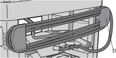
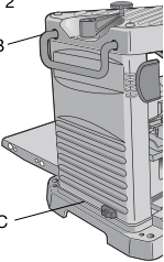
When moving your planer, hold it by the side carrying handles (B) or by the hand indentation (C) at the base of the planer. When transporting or storing the planer, use the cord wrap (D) located in the back of the tool (Fig. 3) to keep the cord in place.
Bench Mounting
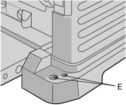
To facilitate bench mounting, two different sized holes (E) are provided on the four corners of your planer as shown in Figure 4. If mounting the planer with bolts, use the larger holes. If mounting the planer with nails or screws...
Depth Adjustment Crank Handle
To attach the depth adjustment crank handle:
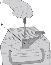
- Insert the crank handle (F) over the shaft (Fig. 5).
- Secure the crank handle in place with the star screw and T-wrench provided.
Dust Hood Installation
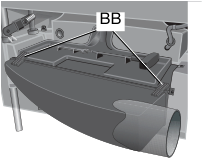
- Remove screws (AA, Fig. 1), save these screws.
- Slide the dust hood clips (BB, Fig. 1A) into place on front of the tool tray and rotate dust hood into place.
Operation
On/Off Switch
To turn the planer on, lift the switch (G). The planer locks on automatically. To turn the tool off, press the switch down.
Table Extensions
Before using your planer, fold down the table extensions in the front and back of the tool (Fig. 7).
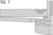
After extended use, the table extensions may be slightly out of level. See Leveling the Table Extensions in the Maintenance section of this manual.
Carriage Head Lock
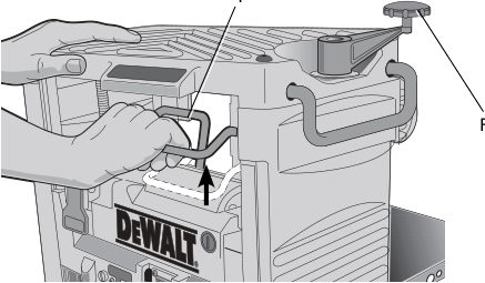
Your planer is equipped with a carriage head lock lever (I) located on top of the motor (Fig. 8).
Depth Adjustment
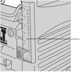
Material Removal Gauge
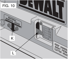
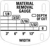
Your planer is equipped with a material removal gauge. It is used to indicate the amount of wood that will be removed in one pass with the carriage set at its current height.
To use the material removal gauge:
- Slide approximately 3” (76.2 mm) of your material under the arrow (K) located in the middle of the carriage (Fig. 7).
- Adjust the carriage height until the desired depth of cut appears on the gauge.
Turret Stop
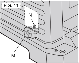
Your planer is equipped with a turret stop, as shown in Figure 11, for repetitive planing of pre-set depths of cuts (1/4”, 1/2”, 3/4”).
To set a planing depth:
- Be sure the carriage is set above 1-1/4” (31.8 mm).
- Turn the turret stop until the desired measurement shows (Fig. 11).
- Unlock the head lock lever (Fig. 8). Turn the depth adjustment crank, lowering the carriage by the desired increments, until it contacts the turret stop.
Planing Basics
To Plane Your Material: Your planer works best on lumber with at least one flat surface.
Snipe
Snipe is a depression made when an unsupported end of your material bends downward, causing the opposite end to lift up into the cutter head.
To avoid snipe, support the workpiece adequately at all times.
To avoid snipe:
- Feed the workpiece into the planer so it is level and remains flat against the base at all times.
Keep long workpieces level throughout planing operation by receiving or "catching" them from the rear of the planer.
Twisted, Cupped and Bowed Wood
If both sides of your material are very rough or if the material is cupped, bowed or twisted, the planer may not produce the desired result. Ideally, you should have at least one level face/surface on your material before you plane. Your thickness planer will work best with material that has been run through a jointer to produce one flat surface. If you do not have at least one flat surface or a jointer, see the following recommendations:
TO PLANE TWISTED WOOD (FIG. 13)
To plane only slightly twisted material: Plane both sides alternating from one to the other until the desired thickness is reached.

TO PLANE CUPPED WOOD (FIG. 14)
To obtain the best possible results with cupped wood: Rip the material down the middle and plane it as two separate pieces.
If ripping the material is not an option: Plane one side of the material until flat, then plane the opposite side until flat (Fig. 15).

TO PLANE BOWED WOOD (FIG. 16)
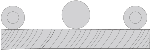
The feed rollers and cutter head in your planer will push the bow out of the material as it feeds. When the material exits the planer, the pressure of the rollers and cutter head will release allowing the wood to spring back into a bowed formation. To properly remove the bow, use a jointer.
CHANGING THE PLANER KNIVES
Your planer is equipped with a three-knife cutter head with three blades that have two sharpened edges. These blades can be rotated once and changed as needed.
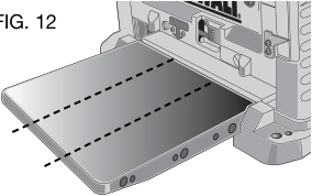
You should change blades when:
- cuts slowly resulting in poor feed
- motor overloading indicating dull knives
- excessive tear-out of wood material
- nicks in blades becoming noticeable
TO CHANGE PLANER KNIVES
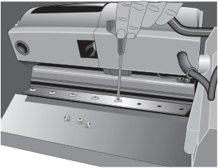
- Use the T-wrench to remove the tool tray. The cutter head should now be exposed.
- If the bolts in the knife clamp ARE NOT visible, use a piece of scrap wood to carefully rotate the cutter head until the bolts are accessible and the cutter head locking lever engages as shown in Figure 21 (O). This will prevent further rotation of the cutter head as you change each knife (Fig. 17).
- If the bolts ARE visible, be sure that the cutter head locking lever is engaged so the cutter head does not rotate while you are changing the knives. To do this, use a piece of scrap wood to attempt to rotate the cutter head. The lever will click into place if it is not already engaged.
- Remove bolts from knife clamp.
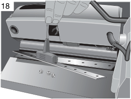
- Use the magnets on the top of the T-wrench to attract the knife clamp and lift the knife out of the cutter head (Fig. 19). One of the knives should now be exposed.
- Use the magnets on the top of the T-wrench to attract and handle the knife. AVOID TOUCHING THE KNIFE WITH YOUR FINGERS. The knives on your planer are sharp.
Maintenance
Routine Maintenance
- Routinely check tool for damage or broken parts.
- Clean any built-up dust and debris that has collected in the accessible areas of the planer from planning wood.
- Wipe off infeed and outfeed rollers.
- Clean base table. Light waxing will help wood material pass through the planer.
- Evaluate blade sharpness condition. Replace as necessary.
- Gauge Calibration, check thickness gauge calibration and test proper calibration.
- Check brushes for wear and replace as necessary.
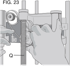
Changing the Belt
- Several tools are necessary to install a belt. The use of a sliding insert wedge (S), as shown in Figure 23.
- With three screws engaged on the large pulley, rotate the pulley clockwise. Keep pressure on the edge of the belt to keep the grooves engaged on the small pulley.
Accessories
There are three accessories available for the DW734 thickness planer:
- DW7351 — Mobile Stand
- DW7352 — 12–1/2" (317.5 mm) Disposable Reversible Planer Knives
Three Year Limited Warranty
DEWALT will repair, without charge, any defects due to faulty materials or workmanship for three years from the date of purchase. For further detail, call 1-800-4-DEWALT (1-800-433-9258) or refer to the warranty information at www.dewalt.com. This warranty does not cover part failure due to normal wear or tool abuse.
DEWALT will maintain the tool and replace worn parts caused by normal use for free anytime during the first year after purchase.
90 DAY MONEY BACK GUARANTEE
If you are not completely satisfied with the performance of the tool, you can return it for a full refund within 90 days from the date of purchase.
Troubleshooting Guide
IF THE MATERIAL DOES NOT FEED PROPERLY, CHECK FOR
- dull knives, rotate or replace as necessary. Refer to Changing the Planer Knives section.
- excess clogging in the dust hood. Refer Dust Hood Installation paragraph in the Assembly section.
- excess oil/debris/pitch on feed rollers. Refer to Periodic Maintenance and Cleaning and Lubrication paragraphs under the Maintenance section.
- excessively twisted, cupped or bowed material. Refer to Twisted, Cupped and Bowed Wood paragraph in the Basic Planing section.
- a broken drive belt. Refer to Installing a New Belt paragraph in the Maintenance section.
- dull knives. Refer to Changing the Planer Knives section.
IF THE CIRCUIT BREAKER TRIPS REPEATEDLY:
- dull knives, dull knives can cause motor overloading, rotate or replace as necessary. Refer to Changing the Planer Knives section.
- reduce the depth of cut, an overly aggressive cut could cause motor overloading. Refer to Depth Adjustment paragraph in the Operation section.
IF THE UNIT DOES NOT RUN, CHECK TO SEE:
- if the unit is plugged in. Ensure unit is plugged into the appropriate outlet, refer to the Important Safety Instructions for All Tools section.
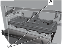
- if the tool tray is properly in place. Refer to Figure 1 for proper location.
- if the circuit breaker needs to be reset. Refer to Circuit Breaker Reset Button paragraph under the Maintenance section.
- if the motor brushes are depleted, replace as necessary. Refer to Brushes paragraph under the Maintenance section.